

超越保险丝盒:雨刮电机电流消耗能告诉你的,电压无法显示的信息

Most bus wiper motors that get replaced are not actually faulty. They are condemned by a checklist that stops one measurement short of the only reading that settles the argument: wiper motor current draw.
Fuse, relay, listen, voltage at the connector, ground, linkage. Those six steps answer whether power reaches the motor. None asks what the motor does with it. Worn brushes, a dry gearbox or a binding output shaft pass all six on a mild morning, then cook on the first cold, wet run of the season.
Picture Monday at a northern depot. A coach arrives with laboured wipers; the technician finds system voltage at the plug and fits a new motor. Eleven days later the coach is back. Neither motor was faulty; both fought a linkage pivot that had been seizing quietly for a season.
This guide is for whoever gets handed that decision rather than the part: fleet technicians, aftersales engineers, distributor support and procurement engineers. It covers why the six-step check stops early, three measurement groups (static, current and park), bench testing, and what to write on the replacement specification. Run wiper motor symptoms and basic checks first.
A note on sources Figures come from published standards, public datasheets or published OEM procedures: the Bosch WDD2 product data, Ford and Mercury service data, insulation values traced to IEC 60364-6 and publicly listed currents from several other makers. Nothing here is a measured guarantee for a model number. The depot scenes are composites: no single coach, no invented readings. They are there to show the order in which a wrong verdict gets made, not to document one job.
要点
- A healthy circuit and a healthy motor are two different measurements. Torque is proportional to current in a permanent-magnet DC motor, so current draw is the closest thing to a torque readout.
- A 150 W class motor on 24 V sits near 10–16 A loaded and 2.5–6 A free at nominal voltage and room temperature. Bands for the class, not values for a model.
- Read the pair, never one figure. High current unloaded points inside the motor; high current only under load points upstream.
- Insulation is measured, not guessed: 500 V DC, minimum 1 MΩ to the case, below 2 MΩ failed.
- Park faults are the most misdiagnosed here. A contact stuck closed keeps the motor fed after switch-off.
Why the Standard Six-Step Check Stops Too Early
The six steps are not wrong; each kills a cheap cause quickly — a blown fuse shows the circuit was overloaded, the relay proves the control side can close, listening separates electrical from mechanical, voltage at the connector proves the harness intact, the ground catches the most common coach-body fault, and the linkage inspection exists because a seized linkage destroys a new motor.
Then most diagnoses stop. Those are different statements:
Voltage tells you whether the circuit is alive. Current tells you whether the motor is healthy.
Three mechanisms hide in the gap. Contact resistance under load: brushes, a pitted relay contact or a corroded pin read full voltage on a meter drawing milliamps, then collapse when the motor asks for ten amps. Losses that never move the supply: a dry gearbox or damaged bearings turn power into heat, and current climbs to meet it. Turn-to-turn shorts: a lower back-EMF constant means more current for less torque.
All three end as heat, which goes as current squared — 40 % more current nearly doubles winding heating. Everything below is what to do when common bus wiper motor solutions do not settle it.
Tools and Safety Before You Measure
The instrument list for this work is short, and all of it belongs in the van:
| Instrument | For | The trap |
|---|---|---|
| DC clamp meter | Current without opening the circuit; the only safe way to read a 50 A stall | Cheap clamps are often AC-only. Check the DC rating, zero it, clamp one conductor — around a whole cable pair the fields cancel |
| Multimeter, 10 A range | Series fallback | The 10 A input is usually unfused and rated ten to thirty seconds, then a cooling wait |
| 500 V insulation tester | Winding-to-case resistance | It applies hundreds of volts: through a rain-sensor module or LIN controller it destroys healthy electronics |
| Milliohm meter | Windings below about 1 Ω | Leads add 0.1–0.3 Ω. Short the probes, note the reading, subtract it |
Test voltage selection
Insulation resistance means nothing without its test voltage. IEC 60364-6 selects it from circuit rating: SELV/PELV at 250 V with a 0.5 MΩ floor; above 50 V up to 500 V at 500 V, 1 MΩ minimum; above 500 V, 1000 V. A wiper circuit sits in the middle row, and going past it means ageing insulation rather than measuring it. The same rating-to-test logic governs which wiper motor compliance and homologation requirements belong in a specification.
Before you touch anything live
A 24 V coach bank is not harmless: two series batteries carry huge fault current, and the injury is usually an arc from a bridging spanner. Disconnect the negative bank lead first, isolate by ignition and fuse, and never plug a connector with the motor commanded on. Retire the test lamp too: it lights because some current flowed, sometimes a few milliamps through the pin you are hunting.
Measurement 1 — Static Checks with the Motor Disconnected
Do all of this unplugged. A motor failing these checks never needed a current test.
Winding resistance
Read for these, not for a target number: continuity where you expect it — an open speed circuit means that speed never engages, not "will not run"; stability as you rotate the shaft slowly, where jumping readings mean commutator segments or brush contact; and reproducibility when you move the leads. Below about 1 Ω use the milliohm method, or you will be measuring your probes.
Insulation resistance
500 V DC, one lead on each terminal in turn, the other on bright clean case metal:
| Insulation resistance to case | Interpretation |
|---|---|
| Below 2 MΩ | Failed — do not return to service |
| 2 – 5 MΩ | Critical |
| 5 – 10 MΩ | Suspect |
| 10 – 50 MΩ | 好 |
| Above 50 MΩ | 非常棒 |
Both conditions apply. The 1 MΩ minimum at 500 V is the pass line, above which the table decides. And temperature: resistance roughly halves per 10 °C rise, so one winding reads twice as badly at 60 °C as at 50 °C — record it every time. A reading recovering after gentle drying points to moisture, and most insulation failures begin life as sealing failure and water ingress rather than as a winding defect.
The five wires you will meet
Wiper motors wire by terminal designation, not colour, and in this family those designations come from DIN 72552, defining everything from terminal 30 (permanent live) and 31 (ground) to the 53 family of the wiper motor itself.
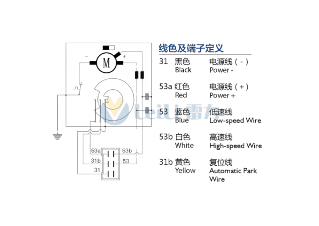
| Terminal | Wire | Role | What you test there |
|---|---|---|---|
| 31 | Black | Power minus, ground return | Loaded voltage drop. More than about 0.1–0.2 V here is torque you are losing |
| 53a | Red | Switched supply | Supply against clean chassis ground, loaded and unloaded; natural place for the clamp |
| 53 | Blue | Low speed | Resistance, then loaded current — compare against high speed, never against memory |
| 53b | White | High speed | Same two checks. Loss of continuity here is the diagnosis for "one speed only" |
| 31b | Yellow | Automatic park | Continuity across a full hand-rotation, plus behaviour after switch-off |
One caution: these numbers are a family, not a guarantee. DIN 72552 puts 53 at the motor input and 53a at the park contact, this definition labels the switched supply 53a, and published tables disagree over 53a versus 53b for high speed. Read the drawing.
The phantom supply a voltmeter cannot see
An oxidised pin on a much-washed coach is a resistor in series. Open-circuit it reads full voltage, because your meter draws nothing; under load it drops a couple of volts out of available torque. Test it as loaded voltage drop across the connection, back-probing, with a wiggle, and repin anything dropping more than the 0.1–0.2 V you already allowed at terminal 31. Some "electrical" motor failures never get past that plug.
Measurement 2 — Wiper Motor Current Draw Under Load: The Number That Decides
Most wrong verdicts come from skipping this section. Nothing else here separates an internal fault from an upstream one as cleanly as wiper motor current draw taken twice, load off and load on.
Why current, and not voltage
Torque is proportional to armature current in a permanent-magnet DC motor. Three consequences follow: current is torque, so it measures the mechanical demand from geometry, arm tension, blade rubber and ice; current is heat, scaling with its square; and taking it free and loaded tells you which side of the casing the fault lives on.
Taking the three readings
| Test state | Setup | What it tells you |
|---|---|---|
| Free | Unbolt the linkage, run briefly on both speeds | Internal losses: brushes, bearings, gearbox, winding |
| Loaded | Everything refitted, glass wetted, record current and voltage together | Installed demand. The number that matters. |
| Stall | Output restrained, energised one to two seconds, once | Upper bound. Useful, dangerous to obtain. |
Stall testing damages both winding and gear train if repeated, so most workshops should skip it and read wiper motor current draw free versus loaded instead. Take wiper motor stall current as a fusing and wiring figure read off the table rather than something to reproduce on the vehicle. Record supply voltage with every reading — a coach charging at 28 V does not give you the reading it gives at rest.
Is that watt an input or an output?
Before any published figure can serve as a reference, settle which side of the shaft it describes:
P [W]     = T [N·m] × ω [rad/s]
ω [rad/s] = 2π × n [rpm] / 60
The Bosch WDD2 (Robert Bosch GmbH datasheet) publishes 50 W nominal with 8 N·m at 60 rpm and 12 N·m at 40 rpm — both give 50.3 W, so its label is shaft output. A publicly listed unit sold as 180 W with 22 N·m at 38 rpm gives 87.6 W: three numbers nobody reconciled. And a 20 W class motor rated 3.0 A at 12 V draws 36 W of input, more than its nameplate, which therefore cannot be input either. That 20 W example also sits below the 50 W class where our bands start, so it appears here as arithmetic evidence and never as a table row. Hence the table below is built by power class, not model number.
Derived reference current bands (50–180 W class, not measured guarantees)
These bands are derived from the published power and voltage ratings using a documented efficiency assumption, then cross-checked against three independent public datasets. They are engineering reference bands for the power class, not measured guarantees for a specific model number.
24 V — the coach standard
| Power class | No-load current | Rated load current | Stall current |
|---|---|---|---|
| 50 W | 0.8 – 1.7 A | 3.5 – 5.2 A | 15 – 21 A |
| 60 W | 1.0 – 2.5 A | 4.2 – 6.3 A | 18 – 25 A |
| 70 W | 1.2 – 2.9 A | 4.9 – 7.3 A | 20 – 29 A |
| 80 W | 1.3 – 3.3 A | 5.6 – 8.3 A | 23 – 33 A |
| 120 W | 2.0 – 5.0 A | 8.3 – 12.5 A | 35 – 50 A |
| 130 W | 2.2 – 5.4 A | 9.0 – 13.5 A | 38 – 54 A |
| 150 W | 2.5 – 6.3 A | 10.4 – 15.6 A | 44 – 63 A |
| 180 W | 3.0 – 7.5 A | 12.5 – 18.8 A | 53 – 75 A |
12 V — four representative classes
| Power class | No-load | Rated load | Stall |
|---|---|---|---|
| 50 W | 1.7 – 3.3 A | 6.9 – 10.4 A (centre 8.3 A) | 29 – 42 A |
| 70 W | 2.3 – 4.7 A | 9.7 – 14.6 A | 41 – 58 A |
| 150 W | 5.0 – 12.5 A | 20.8 – 31.3 A | 87 – 125 A |
| 180 W | 6.0 – 15.0 A | 25.0 – 37.5 A | 105 – 150 A |
A 50 W motor at 12 V works out to 8.3 A — exactly the figure Bosch publishes for its 50 W WDD2 direct drive. That is not a coincidence; it is the efficiency assumption doing its job.
The short version, if you only take one line away: I_rated = P / (η × U), with η taken as 0.40–0.60 (0.50 centre) for a permanent-magnet motor plus worm reduction; I_no-load ≈ 0.20–0.40 × I_rated; I_stall ≈ 3.5–5.0 × I_rated.
The derivation, in full, so you can argue with any step of it:
Step 1  "Rated power" means shaft output power
        Evidence 1 — Bosch WDD2: 8 N·m × 60 rpm × (2π/60) = 50.3 W ≈ its 50 W label ✓
        Evidence 2 — a 20 W unit drawing 12 V × 3.0 A = 36 W input; input cannot be
                     smaller than published input, so the 20 W label must be output

Step 2  Total efficiency η (motor + worm gearbox) = 0.40 – 0.60, centre 0.50
        Evidence 1 — Bosch WDD2, 50 W / 8.3 A / 12 V  →  η = 50/(12 × 8.3) = 50.2 %
        Evidence 2 — the 20 W unit, 20 W / 3.0 A / 12 V  →  η = 55.6 %
        Evidence 3 — a 150 W unit, 150 W / 10 A / 24 V  →  η = 62.5 %, top of the range
        Note: one maker's "motor efficiency 65 %" is the motor alone, before worm losses

Step 3  Rated load current:   I_rated   = P / (η × U)

Step 4  No-load current:      I_no-load ≈ (0.20 – 0.40) × I_rated,  centre 0.33
        Evidence — 1.0/3.0 = 0.33 at 12 V and 0.6/1.5 = 0.40 at 24 V; another maker
                   publishes 2.5/15 = 0.17 and 2.0/10 = 0.20

Step 5  Stall current:        I_stall   ≈ (3.5 – 5.0) × I_rated,     centre 4.25
        Evidence — Bosch WDD2 publishes T_stall/T_rated = 34/8 = 4.25 at its 60 rpm rating;
                   against the 40 rpm rating the same pair gives 34/12 ≈ 2.8, which is why
                   Step 5 carries a range rather than a single ratio. Torque ∝ current in a
                   PMDC motor, so the current ratio tracks the torque ratio
Also worth noting: at 12 V the 150 W and 180 W rows mean 25–38 A continuous with stall past 100 A; one reason coaches are 24 V machines. And where 12 V does carry that, the constraints are copper and fusing: published guidance from another maker puts running current at 3–5 A standard and 10–15 A heavy duty with inrush past 30 A, calls 18–20 AWG inadequate at 15–20 A, and suggests fusing at 25–30 A.
Unsure how much of your reading is motor and how much is load? Send the power class, your steady-state current, and the voltage and ambient temperature it was taken at.
Five reading rules
Read the pair against these five and wiper motor current draw stops being a number people argue about and becomes a verdict:
- Compare like with like — voltage recorded, not assumed, ideally against a second coach on the same route.
- Loaded about 1.4× band, free-running normal → upstream. Work the load side; checking wiper arm spring tension and motor load belongs here, since an over-tensioned arm taxes every sweep.
- Both high → internal: dry gearbox, failing bearing, dragging brushes, shorted turns.
- Below band with weak torque → not healthy. Supply-path resistance, an open brush path and a missing circuit branch all look like this.
- Fluctuating with shaft position → progressing brush or commutator wear.
Temperature: what moves current, and what does not
A 150 W coach motor settles at about 11 A warm. On a February start-up the same motor pulls 14.5 A, 32 % higher. But 14.5 A is still inside the 10.4–15.6 A loaded band for its class, and the rise is almost exactly what −20 °C does to gearbox grease. The correction most write-ups get wrong: copper resistance falls as temperature falls. Copper's coefficient is about +0.4 %/°C, so going from +25 °C to −20 °C takes winding resistance down roughly 18 %. A resistance correction explains nothing here, in either direction.
The mechanism is mechanical: grease viscosity, since the base oil thickens steeply below about −10 to −20 °C and breakaway torque climbs with it; seal and joint friction, because elastomer lips stiffen, repeated at every linkage joint; and external load from hardened rubber, frost, ice and snow.
So expect loaded current at −20 °C to sit roughly 25–35 % above its warm stabilised value, an engineering rule of thumb, not a standard value and not a measured result, to be replaced by your own fleet data. Judge a cold motor against cold readings or another coach in the same hour. Where cold is a standing condition rather than a season, the answer belongs upstream in wiper configuration for different climate zones before it ever becomes a diagnosis. The same upstream logic applies to specifying for duty cycle and motor sizing properly.
The two-speed check
High-speed current ≈ 1.2 – 1.4 × low-speed current, under the same mechanical load.
Published figures for one 150 W class motor give 8 A and 10 A loaded, a ratio of 1.25, and 2.0 A against 2.5 A free, which is the same 1.25: higher output speed means less mechanical advantage and more blade drag. Three verdicts follow. Within the ratio means the speed circuits are fine. High ≈ low points at the speed selection circuit, meaning the relay, switch or module rather than the motor. High lower than low points at wiring, or a linkage refitted out of phase with its stops.
Measurement 3 — The Park Circuit: Why Wipers Stop Mid-Screen
Mechanically, parking is a cam on the output gear operating a switch. Electrically, one contact does three jobs through the conductor labelled 31b, Automatic Park in this family:
- Switch on: current enters at 53a, passes through 53 or 53b, returns at 31.
- Switched off mid-sweep: those circuits die, but the blades are not at rest, so the cam holds the park contact closed and keeps the motor fed. Restoring the supply the driver just switched off is its entire purpose.
- At park: the cam opens it, and the shorting action stops the motor quickly, in the right place.
Every park fault is one of three things: the contact will not close, or will not open, when it should — or it carries current it was never designed to carry continuously.
| Failure | What the driver sees | What you measure |
|---|---|---|
| Contact open or burnt | Blades stop wherever they are, usually mid-screen | The park path never becomes continuous where it should close |
| Contact welded shut | Wipers never stop, or run on long after switch-off | Continuity never drops out; the motor stays fed when dead |
| Control-side fault | Parks only sometimes, stops short, or will not restart | Park line fine; something upstream misreads it |
Note the distinction that condemns healthy modules: the contact carrying motor current and the sense line reporting arrival to a controller are not the same conductor, nor tested alike.
Thresholds worth testing against
| Test | Published threshold | Source |
|---|---|---|
| Park resistance, blades at rest | Below about 1 Ω | Ford Focus procedure |
| Park switch closed | Below 5 Ω | Mercury Mystique procedure |
| Park switch open | Above 10 kΩ | Same procedure |
| Park sense line voltage | Around system voltage running, near 0 V at park | Published across several OEM designs |
Test it with an ohmmeter and your hand:
- Unplug, and find the park terminal in the drawing. Here it is 31b.
- Put one probe on it, the other on that drawing's reference terminal.
- Rotate the output shaft slowly through one revolution and watch for the transition: continuity across the running region, then a clean drop-out at the park angle.
- Read the result. A reading that never changes is your failure, and whether it stays open or stays closed tells you which row of the table above it belongs to.
For relay-driven circuits: sense-line resistance above about 5 Ω reads as open, coils are typically 60–200 Ω, and a closed contact sits below 5 Ω.
Verification, and the expensive consequence
Ten seconds catches what static testing misses: run the motor, cut the supply, watch. It should carry on to the park angle and stop. A motor that stops instantly is not parking — it only worked because drivers happened to switch off as blades arrived. One that does not stop has a welded contact or a stuck relay.
That is how park faults get expensive: continuous current means continuous heat at current squared, and the depot finds a flat battery, a melted plug and cooked varnish next morning. Five minutes rotating for continuity belongs in annual inspection.
Bench Testing: Removing the Motor from the Vehicle
Pull the motor only when the vehicle cannot answer: the readings need a repeatable reference, you are comparing against a known-good unit, the fault appears only under a load you cannot reproduce, or output torque is what you need. Nothing else justifies it. Log every vehicle reading before the first bolt comes out, because removing the motor discards the installed load, which was often the fault.
Supply sizing matters. Ford's published procedure specifies a 12 V external supply loaded to at least 10 A; 24 V above the 130 W step needs 15 A or more; 150–180 W classes need 20 A or more, fused, since stall reaches 63–75 A even for a second. Two series batteries work — fuse it, and prefer a current-limited bench supply.
Work the same stages in the same order, writing wiper motor current draw and supply voltage down at each one:
- Free on both speeds, short runs only.
- Loaded, against a known load or through the arm.
- Stall once, for one second, or skip it.
Efficiency needs no dynamometer. Clamp a lever arm of known length to the output shaft and read tip force with a spring scale:
η      = P_out / P_in
P_out  = T [N·m] × ω [rad/s]      where T = F [N] × arm length [m]
P_in   = U [V] × I [A]            measured at the same instant
With 25 rpm at the shaft, ω = 2.62 rad/s and 180 W of shaft output implies 68.7 N·m; reading 24 V at 15 A gives 360 W input and η ≈ 50 %, exactly what the assumption predicts. Below 30 % means power is going somewhere other than the shaft, usually the gearbox. Accuracy is limited by the spring scale, so compare two candidate motors.
Refit without creating the next job. Mark the crank arm relative to the shaft before unbolting: park mechanisms are phased to the output, and a link one spline out of phase parks correctly on the bench and wrongly on the windscreen. See 如何测量雨刮器连杆的尺寸 for the dimensions worth taking.
Building a Decision Tree: Replace, Repair, or Look Upstream
Read wiper motor current draw alongside every other result below, never on its own, and this becomes a routing decision rather than a judgement call:
| What you measured | Meaning | Next step |
|---|---|---|
| Free and loaded both high | Internal: gearbox drag, bearings, brushes, shorted turns | Replace, or repair if brushes are serviceable |
| Free normal, loaded high | Upstream load fault | Leave the motor; fix the load side |
| Both below band, torque poor | Resistance in supply path, open brush path, missing branch | Check connector drop and pins first |
| Fluctuates with shaft angle | Brush or commutator wear | Plan replacement at the next window |
| Supply voltage sags under load | Wiring, connector or ground fault | Repair the circuit, then re-measure |
| Park line never continuous | Contact open or burnt | See Measurement 3; often repairable |
| Park line never opens | Welded contact or stuck relay | Replace that part now |
| Insulation below 2 MΩ after drying | Insulation breakdown | Replace; find out how water got in |
Start with seizing linkage pivots: the most common cause of repeat failures, and the one item here that no six-step electrical check can clear. Then, roughly by frequency: arm spring tension above specification, worth checking properly rather than by feel against wiper arm spring tension and motor load; hardened blades and the dry, hot duty that accelerates them, covered in our summer wiper system maintenance checklist; glass film; undersized wiring; and geometry that drifted after a body repair.
Nobody publishes this one: ask an experienced depot foreman how many motors he has replaced where nothing was wrong with the old one, and the answer is usually near half. Treat that as a rule of thumb rather than a statistic, and take it as a standing instruction to record loaded current on every removal you authorise.
What to Specify When the Verdict Is "Replace"
A diagnosis is only useful if it changes the order. Working backwards:
- Voltage with its window — 12 V or 24 V as a range, not a point: for coaches, what a bus network presents under ISO 16750-2 including cranking and charging.
- Power class against the measured load, not the old label. Top-of-band readings justify one class up; a mechanical fault is untouched by any class change.
- Output torque and speed together, since one alone cannot be checked, and P = T × ω audits a datasheet in about sixty seconds. See wiper motor parameters torque power and protection.
- Stall torque margin, which decides how much abuse from a frozen blade the motor absorbs before something yields.
- Park function written out explicitly — behaviour, terminal numbering, connector and pinout. This prevents more installation faults than anything else here.
- Mechanical interface: shaft form, gear tooth count, bolt circle, crank phase, rotation direction. Ask for drawings — ours show roughly 15.6–15.7 mm shafts, a three-bolt Ø90 pattern and 25/38 rpm in the larger classes.
- Duty and environment in writing: temperature range, duty cycle, wipes per day, and the ingress rating genuinely needed. Stating our own position plainly rather than borrowing anyone's claims: our parts publish to IP52, and a duty needing a vehicle-code rating belongs at specification stage.
Want the specification sheets and drawings for the power classes above? Ask your usual contact.
常见问题解答
What current should a 24 V bus wiper motor draw?
Derived bands run from 3.5–5.2 A loaded for a 50 W class motor up to 12.5–18.8 A for 180 W, with free-running figures roughly a fifth to a third of those. A 150 W class motor, the usual city and coach size, sits near 10–16 A loaded and 2.5–6 A free. Those are wiper motor current draw bands at nominal voltage and room temperature, not limits for a part number.
Current is normal but wipers are slow — is the motor at fault?
Usually not, and it is the most misdiagnosed case. In-band current means full torque; something is absorbing it. Move the linkage by hand, check shaft play and gearbox backlash, verify crank phasing.
Can I check brush wear without removing the motor?
Partly: free-running current climbing across a season; stability as the shaft rotates, where rhythmic fluctuation means a commutator segment; supply ripple if you have a scope. Real inspection means removing the end cap.
How many megohms is acceptable?
At 500 V DC the minimum traced to IEC 60364-6 is 1 MΩ to the case, and motor-condition guides grade higher: below 2 MΩ failed, 2–5 critical, 5–10 suspect, 10–50 good, above 50 excellent. Record winding temperature with it.
Can the park switch be replaced separately?
Where it is a plate under the gearbox cover, yes, with a reseal and a park verification run. Built into the connector or controller, replace the assembly. Always ask why it failed.
结论
It comes down to one habit: take wiper motor current draw twice, load removed and load fitted, and write the supply voltage beside both readings. Whatever survived the six-step check usually stops being ambiguous at that point.
For the workshop wall: free-running high points inside the motor; loaded-only high points upstream; a park line that never opens will cost you a motor.
None of them demands more than a clamp meter, an ohmmeter and writing the supply voltage beside every reading. Ten minutes spent measuring a healthy vehicle today becomes the reference you argue from six months from now — and our commercial vehicle wiper troubleshooting guide carries that habit across the whole system.
标题与内容的对应关系说明(撰稿人备注,中文)
标题已按 Yoast 主关键词 wiper motor current draw 重拟,三段的承诺与文中承接位置如下:
① Beyond the Fuse Box —— 由「Why the Standard Six-Step Check Stops Too Early」承接:逐一点名 fuse/relay/listen/voltage/ground/linkage 六步后立刻指出共同断点(只证明电到了),并立起"电压说明电路活着,电流说明电机健康"这一方法论标签(正文仅此一处以 pull-quote 出现,结尾不再重复);此处也是与站内 #9(30211)的边界处理方式——只引用、不重复六步操作细节、不列泛化症状清单。
② What Wiper Motor Current Draw Tells You —— 由 Measurement 1/2/3 与 Bench Testing 四章承接:静态检查(绕组读数看什么、500 V 绝缘五级分值、DIN 72552 五线端子辨识及"编号是族不是保证"的诚实提醒、虚电压降)→ 带载电流(P=T×ω 口径判定、两张推算参考区间表 + 一句可引用公式摘要 + 五步推导链 + Bosch 8.3 A 钉子句 + 12 V 大功率档线径与熔断约束、判读五规则、低温机制纠偏、双速比判据)→ park 回路(31b 三步时序、三类故障电气特征、端子级阻值阈值、四步手势測試法、十秒验证与"触点粘连烧机"连锁后果)→ 台架(按功率档的电源规格、三段法、η 弹簧秤粗算、重装防错)。
③ That Voltage Cannot —— 标题的对立轴在文中落在三处:Measurement 2 的「Why current, and not voltage」与「The phantom supply a voltmeter cannot see」两节,以及 Decision Tree 表格中"两者都低于区间且扭矩差=供电路径电阻"这一行——即用同一个电流读数反证纯电压测法的失效区间。
④ wiper motor current draw 一词的实际分布 —— Measurement 2 章标题、该章首段导语、堵转段、判读五规则导语、台架三段导语、Decision Tree 导语、FAQ 首答与 Conclusion,共 9 处,均见交付报告中的词频与行号清单;首次出现已在首段前 40 词内。
⑤ 三条外链均为一手来源:IEC 60364-6:2016(IEC Webstore 官方页面,已实际访问确认)、DIN 72552-2:2014-07(DIN Media 官方页面,已实际访问确认)、Bosch WDD2(Robert Bosch GmbH 官方产品数据表 PDF,已下载并由文本抽取逐项核对 50 W / 8,3 A / 60–40 rpm / 8–12 N·m / 34 N·m / 76:1)。三者均作引用与溯源之用,不作竞品对比。
如需再压缩篇幅:优先砍 Tools and Safety 与 FAQ;Measurement 2 的两张表、推导框、判读五规则、温度纠偏、双速判据与 Measurement 3 的 park 阈值表务必保留。
.png)


