
I. Selection Is Not About Picking Specifications, but Solving a Set of Constraints
Many people imagine wiper assembly selection as taking a product catalog, comparing parameters such as motor power, wiper blade length, and ingress protection rating, and picking a suitable combination.
The reality is different. The components of a wiper assembly are strongly coupled: a longer wiper blade increases the sweep area but raises the torque requirement on the motor; once motor torque goes up, the reduction mechanism and linkage must increase their strength accordingly; if the linkage layout changes, the designer must reconfirm the parking position and sweep phase of the wiper blade.
So selection is more like solving a set of mutually constraining requirements than adding items on a checklist. This article breaks the problem down in the order of an actual matching process.
II. Step One: Start with the Windshield Geometry
Everything starts with the glass.
The size, curvature, and rake angle of the windshield determine the basic framework of the wiper assembly. What needs to be confirmed includes:
- The visible area: regulations and actual driving needs jointly define the area in which the driver must maintain a clear field of view. The wiper sweep area must cover this region, rather than simply being “the bigger the better.” If the sweep range extends beyond the edge of the glass, the wiper blade will flip over, make abnormal noise, and wear faster.
- Glass curvature: curved glass requires the wiper blade to conform throughout the entire sweep stroke. Glass with large curvature changes places higher flexibility demands on the wiper blade and also affects the design of the linkage’s motion path.
- Space below the lower edge of the glass: the wiper parking position is usually hidden in the decorative area along the lower edge of the glass. The depth and shape of this space determine the posture of the wiper arm when retracted.
The conclusions from this step are usually: the sweep angle range, the upper limit of wiper blade length, and the parking position.
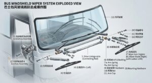
bus windshield wiper exploded view
III. Step Two: Determine the Sweep Solution
With the boundary conditions of the glass established, the next step is to determine how many wiper arms to use and how to arrange them.
Common configurations include opposed sweeping (left and right wipers sweep from the sides toward the center) and parallel sweeping (left and right wipers swing in the same direction). Opposed sweeping is more common on buses and large glass areas, as it can cover a wider field of view; parallel sweeping has a relatively simpler structure, and engineers more often use it on models with narrower cabs.
The specific issues to resolve at this stage include:
- Whether the sweep areas of the left and right wiper blades leave any gaps, and whether an unwiped triangular zone remains in the middle.
- Whether the two wiper blades interfere with each other during motion.
- Whether the wiper blades are fully hidden within the decorative area when parked in the initial position.
- Whether the ends of the wiper blades extend beyond the edge of the glass at the extreme sweep positions.
These questions can be calculated on drawings, but in the end they often need to be verified on an actual vehicle or with prototype parts. Glass is curved, and there is always a gap between paper calculations and actual conformity.
IV. Step Three: Match the Motor and Linkage
Once the sweep solution is set, the power requirement can be calculated.
How Is the Torque Determined?
Friction exists when the wiper blade conforms to the glass, and this resistance is related to blade length, pressing force, and whether the glass is dry or wet. Resistance during dry wiping is significantly greater than during wet wiping, and the design must consider the most unfavorable condition—that is, when the glass is nearly dry and the wiper blade must overcome greater friction.
Only after the torque requirement is determined can motor selection and reduction ratio design have a basis. A common mistake here is selecting based on normal operating conditions, which results in weak wiping and a noticeable drop in speed in actual use.
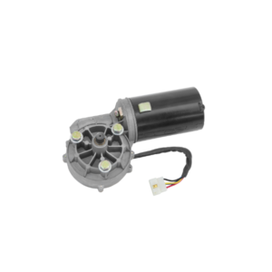
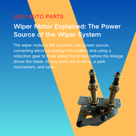
wiper motor unit
Linkage Layout
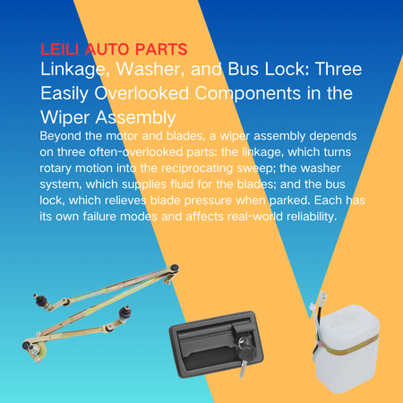
The linkage must simultaneously satisfy three conditions: accurately converting the motor’s rotation into oscillation at the specified angle, routing within the vehicle’s packaging space, and keeping the forces at each pivot point within acceptable limits.
Front-end packaging space is usually very tight, and the linkage routing often has to go around other components. Once the routing changes, the rod length, pivot positions, and force directions must all be recalculated. This is also why the linkage is often one of the last components to be finalized.
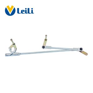
NLG-022 Wiper Linkage
V. Step Four: Positioning the Washer
The washer seems like an independent small system, but the vehicle layout heavily constrains its position.
Nozzles are generally mounted on the engine hood, wiper arms, or front cowl trim panels. Different mounting positions lead to obvious differences in spray angle and coverage. Design considerations include:
- Whether the spray point falls within the wiper blade’s sweep path, so the fluid can be wiped away promptly after spraying.
- Whether airflow during vehicle travel will deflect the sprayed cleaning fluid.
- Whether the nozzles are easily clogged by mud and dirt, and whether they are convenient to reach for maintenance.
- Whether the reservoir capacity and mounting position meet the refill frequency needs of actual operation.
Commercial vehicles and buses operate at high intensity and consume washer fluid quickly. Therefore, designers often pay more attention to reservoir capacity and refill convenience than in passenger cars.
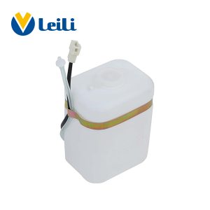
plastic washer tank for car windshield washer system

VI. Step Five: Verify Under Actual Operating Conditions
Once the design is finalized, it needs to be verified whether it holds up under real conditions.
Verification usually centers on several categories of conditions:
- Environmental adaptability: operating status under high temperature, low temperature, temperature cycling, and hot-humid environments.
- Corrosion and aging: the effects of salt spray and UV exposure on metal and rubber parts.
- Durability: whether components show performance degradation after long-term repeated operation.
- Vibration and shock: whether fasteners loosen and whether mechanisms produce abnormal noise under vehicle vibration conditions.
- Electrical compatibility: whether it works properly with vehicle voltage fluctuations and control signals.
It should be noted that different vehicle models have different verification priorities. City buses focus more on durability under frequent start-stop operation, construction machinery focuses more on sealing in dusty and muddy environments, and long-haul commercial vehicles focus more on adaptability across the full temperature range. Using a single unified verification plan to cover all vehicle models often misses the real weak points.
VII. When Should the Supplier Get Involved?
The process above reveals a pattern: the later you make a decision, the more deeply earlier ones constrain it.
If a supplier joins after the OEM finalizes the drawings, it can only “make something that fits the given space.” It cannot propose optimizations on sweep angle, linkage routing, or motor power.
Early involvement pays off. The supplier can raise the wiper’s kinematic constraints while the glass geometry and vehicle layout are still changing. The supplier can thus avoid passive modifications later later due to insufficient space or unsuitable angles. For OEMs, this usually costs far less than modifying tooling later.
VIII. Conclusion
Wiper assembly selection is essentially translating a curved piece of glass, an installation space, and a set of operating conditions into a set of specific component parameters. There is no standard answer to this process—only whether the result matches the vehicle model.
For buses, construction machinery, and commercial vehicles, operating conditions vary widely and usage intensity is high, making matching accuracy especially critical. Rather than pursuing margin in specifications, it is better to understand each constraint clearly and let the solution truly land on actual operating conditions.


.png)